Thursday 15 September 2011

If you don't like what you see, buy a new mirror

Household mirrors are designed to withstand the usual attacks by toddlers/angry teenagers/flying objects and for that end are back-surface coated. This means that you have a sheet of glass on the back of that sheet is the refelctive surface. That way, the reflective coating is protected by the glass which can be conveniently wiped down. This feature however makes it unsuitable to deflect the picture of a projector.

At the point where the projector output hits the mirror it is still unfocused. Before and after the unfocused picture is reflected by the reflective surface it is refracted by the glass. This has the effect of the picture not focussing correctly on the screen anymore, also known as 'ghosting' (see picture below). I didn't do the raytracing of how this happens because I feel exploring that issue in such depth would be a waste of time.

Ghosting effect when using a household mirror. Above and below the actual object are shadows which result from the unfocused picture not being deflected uniformely. Walls and everything else are equally affected, but it's less obvious.

To resolve this issue, we needed a front-surface coated mirror. These are by far more delicate as they can easily scratch. After some research I ordered one from Knightoptical with enhanced aluminium coating (just as a reminder, it's 140mm in diameter). This is, as far as I know, the cheapest coating to reflect the entire spectrum of visible light.


Front surface coated mirror. It even comes with a protective film!
Like the previous mirror, I mounted the mirror on an L-shaped piece of scrap metal. Just make sure to fasten the nut tightly so the mirror doesn't slip.

It is thicker (6mm) than the household mirror I had before, but, to my surprise, wasn't much heavier which I thought could be problem if the right-angle joints I'm using to hold the mirror are not strong enough.


Here is the result: No ghosting anymore. You still see a slight glow or blur around the edges in the picture but that's only the camera struggling with light shining into the lens. You can still see the light overshooting the mirror, but this will be resolved soon too.

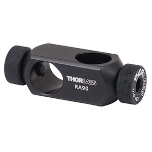
On a sidenote, I've replaced the Thorlabs 90 degree angle joints with Newport joints because you can fasten them much tighter and they easily withstand knocks and vibration. The Thorlabs joints I had to tighten every so often because the screw that presses against the post to hold it comes loose easily. Generally I choose the brand depending on who I feel has the better solution for a given part.


Thorlabs (top) and Newport (bottom) angles. As you can see the Thorlabs joint only has a screw pressing against the post to fasten whereas the Newport joint actually clamps onto the post. Both pictures are property of the respective companies.

Results
With the new mirror installed the ghosting effect is completely gone. Further, because the formerly scattered light is now focused where it should be, contrast and brightness have improved noticeably. However I still think I need to do one or two things to improve picture quality, but this is definitely a step in the right direction.

Thursday 1 September 2011

Computer Mouse Surgery (Motion Tracking)

Having a mouse run around the virtual reality requires tracking movement of the mouse (i.e. the treadmill) and updating the location in the virtual reality accordingly. The cheapest system for motion tracking are optical computer mice, placed stationarily at the equator of the spherical treadmill. Apart from being cheap, computer mice are also very easy to interface with the computer. Hölscher et.al. (2005) have succesfully used this system and so have Harvey et.al. (2009), and so will I.

One of the technical difficulties is that the lens has to be very close to the surface of the treadmill, and even small changes in distance can cause problems in tracking motion. Recently, mice with laser instead of normal light are becoming available which are more precise and also seem to tolerate changes of distance between sensor and surface better. After a few tests I decided to use one of the standard issue Dell mice:

The mouse used for motion tracking. Very cost efficient and shows good performance. Dell calls it almost affectionately "Dell Laser Scroll USB (6 buttons scroll) Black Mouse'

One of the potential downsides of this unit is that it has an inbuilt function to change cursor speed. This might cause problems later on because I need a 1:1 mapping between mouse-movement and input to the computer. I will explain this further in a later post.

First of all I had to remove the housing of the computer mouse and take out the parts that mattered, which is essentially just one PCB board. I would like to show you pictures of the gutting process, but alas I've done that to so many computer mice before this one that I stopped documenting it. My desk is a computer mouse graveyard. Soon enough I will need a second one of these though, at which point I will upload a post with pictures of every step.

After taking out the PCB board I also found out that this mouse has a very handy construction feature: the lens for the laser and camera is directly mounted on the chip (unlike most other mice where it is attached to the housing). So I can just take the PCB out and have a fully functional mouse:

The underside of the computer mouse PCB. In the centre you can see the lens.
To allow the mouse to track the motion of the treadmill we need to bring the bottom surface of the lens as close as possible to the surface of the ball without touching it. To do that we need something that holds the PCB board. I guess it's redundant to say that the combination of 3D-modelling software and 3D-printing came in very handy here.

A 3D model of the mouse holder. The pole at the bottom is 1/2" in diameter so I can mount it like any normal post on the airtable. The other features are easier to explain when you see the finished thing.


The PCB board slots in like this, exposing the lens quite well. I only had to make minor adjustments because apparently my measurements were not 100% correct.
The PCB board is fixed like this. A screw, that just happens to have exaclty the right length, presses down at the board at a point where there are no components. I realise the screw can come lose quite easily, should that become a problem I will just put some Loctite on the thread.
Because 3D printing is neither precise enough nor strong enough to make a thread for a screw I left a slot for a nut. To my surprise it fitted in absolutely beautifully, no need for glue or anything. The cutout on the top right makes space for the USB cable.

You can see a small rectangle cut out in the picture above, this is where the connector for the USB cable is located. Simply plug in the cable and then connect it to the computer like you do with a normal mouse (see picture below).

Results

After putting everything together there wasn't much to do other than to mount it on the airtable and see how it works. The mounting angle turned out to be a problem here. The base of the treadmill didn't leave enough space to mount the mouse straight on the equator. This meant I had to angle the computer mouse a bit and mount it further up which in turn required me to mount it vertically rather than horizontally as I had .planned initally. This means I needed more space for the posts, which is suboptimal because there isn't much space left (micromanipulator) and right (head restraint). The next generation of the 3D-model will resolve this problem, at a price of less than £100,- per 3D-print, one or two protoypes are within budget.

A first test showed that movement along the horizontal axis is picked up very well (i.e. running forward and backward), however, movement across is tracked rather poorly. This means I will need a second mouse mounted 90 degrees to the current mouse to pick up sideways movement, as it has been done in the two setups before me (Hölscher et.al. 2005 and Harvey et.al. 2009).

 
This is how it is mounted right now. Not ideal, but this will be resolved in the next generation of the 3D-model of the holder. The clearance is as small as possible, but small movements of the ball have to be taken into consideration.

Update
Here is the link to the follow up post: http://mousevr.blogspot.com/2011/10/apples-and-oranges-that-look-like.html

References

1. Harvey CD, Collman F, Dombeck DA, Tank DW. Intracellular dynamics of hippocampal place cells during virtual navigation. Nature. 2009;461(7266):941-6. Available at: http://www.ncbi.nlm.nih.gov/pubmed/19829374 [Accessed September 20, 2010].

2. Hölscher C, Schnee A, Dahmen H, Setia L, Mallot H a. Rats are able to navigate in virtual environments. The Journal of experimental biology. 2005;208(Pt 3):561-9. Available at: http://www.ncbi.nlm.nih.gov/pubmed/15671344 [Accessed June 15, 2011].