Friday 28 September 2012

Go Rebel

The inferior performance of the previous LED lighting system meant that it was unusable under high magnification. Straight after that first attempt I ordered a new set of LEDs that have a significantly higher rating.

The Philips Luxeon Rebel series of LEDs come in various wavelengths and third parties offer lenses and baseboards for them. To recap: I need my light system to fulfill three requirements:
a) small size so it fits into the system
b) bright enough to allow working under high magnification 
c) narrow light beam so that the bright light doesn't disturb the animal

So for the next generation of my light system I picked what is technically an RGB mixer lens which produces a  +/- 6° beam + baseplate that doubles as breakout board for the LED contacts and a heat-sink mounting point. Instead of Red, Green and Blue I just put in 3 high-power white LEDs.

a) Small Size so it Fits into the System

When the LEDs arrived it became clear that size won't be an issue. In fact, one problem with the LEDs is how small they are. Don't be fooled by the amount of light they are producing, they are about 2 x 5 mm. On that space are 3 contacts: cathode, anode and heatsink. All of which are in the same plane on the underside. This means, arranging 3 LEDs so that they are connected in series AND have good contact with the heat sink becomes next to impossible. Luckily there are also baseplates available which break out the contacts and allow to easily to attach a heatsink to its bottom.

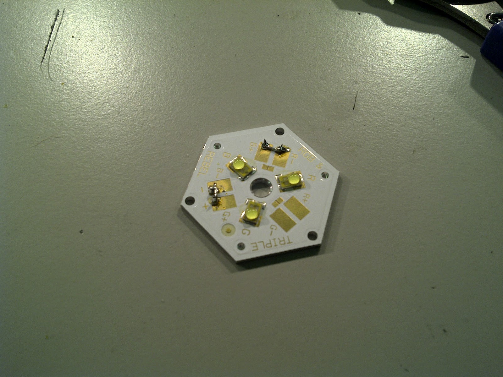
Luxeon Rebel Tri-LED breakout board. Apart from the insulated contacts this is made of aluminium for good heat transfer to the heat sink that goes on the underside.


One LED on a tape measure to see the size of them. In the bottom picture you can see the three contacts.

While it is possible to put solder on all of the contacts, heating the contacts all up again to solder them down is next to impossible because they need to sit flat on the baseboard and there is no way to access to contacts with a standard soldering iron once they are in place.

A technique called reflow soldering was the best way to deal with this problem. In brief, you apply a paste that contains solder to the contacts and stick the components together. This is followed by applying heat until the paste melts and turns solid. I haven't used this technique before, but it seemed straightforward enough and there is a great tutorial on the Sparkfun website how to do this with a skillet (or any hot surface for that matter). 

After finding a workshop that had some soldering paste (easier said than done) and finding a hotplate (which we usually use to gently heat and stir delicate solutions...) I carefully applied paste to the contacts and popped the LEDs on it (see pictures below). After that I slid it on the hot-plate and waited a few seconds until the solder melted and made contact with the LED.

Apply solder paste
Pop LEDs on, push them down a little bit but make sure that paste on cathode and anode doesn't make contact 
The hotplate. Exciting, I know.
Put on hotplate for a brief period to melt solder paste. Also, in this picture you can see that I simply connected the breakout contacts of the LEDs in series. And of course the cable will be soldered onto the last two contacts.

Instead of building my own circuit to drive the LEDs I decided to invest into a LED driver. Very conveniently it takes 24V DC input and produces 3 - 33V output (depending on how many LEDs are connected in series) at 1000mA max. current. It has a an analogue and digital dimmer pin to adjust brightness. 

One problem with such powerful LEDs is thermal management. The LEDs have a maximum temperature of 135°C, which means you can run them at full power without a heat sink for about 5 seconds before they blow (or melt?). The baseplate provides a small amount of cooling, but far too little. While one can go into long and complicated calculations how much heat-dissipation is required I simply picked a generously sized heat sink, some heat-transfer tape and stuck it to the baseplate. Well... it wasn't enough. I ended up combining two heat sinks until I felt comfortable with the amount of dissipated heat (which I professionally assessed by touching the heat sink every minute or so and checked how hot it is). There is a heat sink calculator on this excellent website but I ended up not using it as I had the heat sinks ordered before I discovered it.

LEDs on double heat-sink. Between baseplate and heat sink is thermal transfer tape.
The lens for the LEDs fits perfectly and slots into the baseplate. I've used some superglue to fix it, hoping that the LEDs stick to their promise of lasting for the next 9001 (or so) years.

Lens that goes over the LEDs.

b) Bright Enough to Allow Working Under High Magnification   

The brightness of this assembly is really quite remarkable. I've made the mistake of looking straight at the LEDs without the lens on when I turned it on for the first time. It took a while until I regained full vision. Each of these LEDs at full power (i.e. at 1000mA (!!) ) produces 310 lumens according to the manufacturer. These LEDs are rated in lumen rather than microcandela (mcd) which makes it hard to compare to the previous set of LEDs I had and it is difficult to convert between these units so I won't try. According to the internet, a 60W incandescent light bulb has about 800 lumens. Keep in mind that a 60W bulb can light up an entire room quite easily. My LEDs with the lens focus ~85% of its 930lm in a +/-6° beam. Here is a comparison between the two systems I've made:

The old system: seven "super bright" LEDs, at 2.5 cm, focused in one point.
The lightcano.

c) Narrow Light Beam so that the Bright Light Doesn't Disturb the Animal 

This is the only point in which the new LEDs lack behind the previous system. The lenses are not focusing the light well enough. That said, I could build a shield to focus the light in a narrower beam. However, I've found it easier to make a little cover that blocks the light from shining directly into the mouse's eyes without blocking the its view onto the virtual reality screen. While the mouse can still see the entire environment lighting up, none of the intense light is frying its retina.

Conclusion 

Having tested the new lighting system in an experiment and compared it to the old I can say that the difference is like day and night - literally. A key disadvantage of the new system is that the light is less focused and therefore I can't avoid the eyes of the mice but with a small shield this problem is easily circumvented. An upside of the light intensity is the fact that I can place it further away, and therefore its even less in the way. The fantastic brightness means that whatever worries I had about illuminating the brain surface are now gone.

Friday 7 September 2012

The Good, the Bad and the Ugly

A key consideration if one wants to do electrophysiology on a virtual reality rig is space for all the required equipment. One such thing is the light source. Ideally it only lights up a small area so that the animal won't be stressed or disturbed by the sudden bright light. To get an ideal solution for this I decided to make a frame for LEDs that would allow me to shield stray light and place it just where I needed it using a snake-arm on a magnetic base.

The Good

The light-source, like all other bits of equipment for this project, will be used in a clean facility. That means no loose cables or half-done jobs. However, to drive the LEDs a small circuit was required that would provide the right current and voltage. Further, being able to dim the LEDs might be beneficial. Less light means less disturbance for the animal. And of course, a nice enclosure makes everything look a bit more professional.

Box and frame. No electrical safety test was required as only 24V DC is going into the housing.

The top of the box features an on/off switch and a knob that dims the LEDs. Of course the knob is just a potentiometer underneath. The box is made of plastic, but the quality is good and it comes with anti-slip pads so that it sits on any surface quite firmly. Drilling the holes to fit switch and potentiometer through was even easier than drilling the aluminium frame for the heating mad system.

The second part of the system was the holder for the LEDs. I decided that using 7 "super bright" white LEDs will be sufficient. The description on the seller website said they are so bright that looking into them directly would hurt your eyes. Well, I thought, if one hurts your eyes, seven must burn your brain. And falling short of that, still enough to illuminate a work surface.

These LEDs are designed to emit light at a 20 degree angle, accompanied by some stray light, suiting my application quite well. While using a convex lens would have been the more elegant solution to focus the light I opted for the cheap and easy way of just shielding any unwanted light. With so many lumens at my disposal, shielding some won't be a problem, or so I thought.

The Bad 

Unfortunately, it turned out that the "super bright" white LEDs are not as bright after all. While it is true that they are unpleasant to look into, it's nowhere near bright enough to light up an area to look at it under high magnification. Even when 7 of them are focusing on point only 4cm away from the LEDs it didn't produce enough illumination. While in the picture below it certainly looks like the LEDs almost burn a whole into the table, it really wasn't that bright. Add the fact that they can't be placed at the ideal angle to shine onto the surface of the brain and it becomes rather useless.

~4cm distance from LEDs. While the light is nicely concentrated in one spot it didn't produce enough illumination, the picture is quite misleading.

One problem with using a simple potentiometer to alter the voltage on the LED for dimming is that LED have an exponential voltage response. That means that low voltages for large parts produce almost the same (low) amount of light, and only the last few hundred mV approaching the LEDs max. voltage rating produce a huge change in response. However, LEDs are very sensitive to applying too much voltage, which means if you turn the pot too far you will fry the LEDs. That is also the reason why proper LED drivers are a bit more sophisticated.

Luckily, in the process of soldering up the LEDs a friend from the workshop showed me some real LEDs. These are industry-grade, not some hobby-project components. They hurt your eyes even when standing on the other side of the room. Exactly the kind of thing I needed. On top of that a real LED driver (which can be bought for <£20.-) will be used instead of just a potentiometer, allowing dimming the LEDs linearly.

The Ugly

Approaching the halfway point of my PhD at an alarming pace I decided that time is becoming a currency ever-increasing in value. It makes a lot of sense, therefore, to save time where possible, even at the risk that one of my contraptions won't last for the next 50 years. While some soldering couldn't be circumvented, I decided to use a mini-breadboard and some jumper-wires to assemble the circuitry inside the box. With hindsight, it didn't save an awful lot of time, but at least it made it a lot easier to assemble and take apart again in case there were any mistakes in the circuitry.

This might fall to pieces the first time someone knocks it but until then it will do the job. If I can find a glue-gun I'll just glue it all down.

Instead of using a double-stranded wire I used two single-stranded ones (blue and red) to connect the LEDs. That was purely for the reason that I didn't have a double-stranded one available and I needed to get this up and running.

Conclusion:

Arguably it is a viable option to simply buy an off-the shelf lightsource with some gooseneck light-guides. However, designing your own lighting system guarantees that it will fit exactly where you want it and only illuminate the area required. While my current solution is suboptimal due to low light output, the next generation will hopefully do the job.

Tuesday 8 May 2012

Thinking Inside the Box (Heating Mat DIY part 2)

Here is the long promised follow up to this post.

In brief: I want to build a heating mat that keeps animals warm while under anesthesia. Three components are required for that: a heating blanket, a thermometer (thermocouple to be correct) and a PID controller that regulates the heat output to keep it at a set point. In other words: if the mouse body temperature drops, the heating mat gets warmer to compensate. In the previous post I put together such a system on a prototyping board and here I document how I put this system into an instrument case for use on a bench.

The reason why I made an effort to put everything inside a well organised case and not just throw the prototype onto the bench is threefold:
  1. We will use this during surgery in a sterile environment, therefore having something that can be cleaned easily is imperative.
  2. Everyone should be able to use it, not just myself. For that reason it is important to keep it simple and intuitive.
  3. Any instrument used in the office or lab needs to pass electrical safety testing and I have serious doubts my protoype with exposed mains contacts would have fared well in the test.
  4.  

The Box

While there are loads of generic instrument casings out there I decided to take a nice one to make the instrument look as professional as possible from the outside. After all, it has to blend in with other top notch scientific equipment. More importantly though, I don't want to give our beloved and omnipresent health and safety inspector any reason for concern. She really has enough on her plate with untidy cables, sharp screwdrivers murder weapons lying around and expired electrical safety stickers. Truly, we are blessed with a guardian angel who spots danger where lesser people (such as myself) stare certain death in the eye without even noticing.

To keep things simple, there is one mains connector and power-switch at the back. At the front we have the connector for the thermocouple and the heating mat along with the PID controller display and the buttons to program it. The heat-sink is screwed straight onto the back panel with the op-amp mounted onto a thermal transfer pad on the other side of the panel. Since heat-sink as well as panel are made of aluminium there won't be any trouble with heat-transfer.

The layout idea.
The mains inlet contains a 1A fuse. It wasn't that easy to wire up mains connector and power switch. It's one of those things where every seller assumes that you know what to do and therefore don't provide wiring diagrams.


The most time-consuming work after soldering was to cut the front and rear panel. For that I used a mill to cut around the edges. This was followed by filing the corners until the part fitted in. It doesn't have to be the cleanest job in the world as all panel-mounted parts have some extra cover material around the edges to hide the ugly.


Milling
Filing
Placing the part. They either clip in directly or have a retention clip.

Rear panel done.
Repeat for front panel.

After clipping in mains inlet and power switch as well as heatsink I placed the amplifier in the case. After that I grounded  the front, rear and side-panels for safety reasons. Top and bottom panels as well as corners of the case are not conductive and therefore don't need to be grounded. Finally, the rest of the components just about fitted in and I was able to put the lid on the case.


One policy regarding instrument safety around here is that if there is a mains-cable running into a device the housing needs to be safety-grounded. Therefore all conductive panels are connected to the earth of the mains inlet at the back.

Add the 12V DC power supply for the heating mat, put in the PID controller as well as the connectors and this is good to go. In the top right hand corner you can see the op-amp and the heat transfer pad.

Once the lid is on, the chaos is gone.


Blanket

Instead of soldering the heating blanket directly to the output I wanted it to connect to the outside of the box. That way it was interchangeable so if it breaks or has to be exchanged for some other reason there is no need to open up the box. We chose a simple 3-pole connector that is usually used for microphones but has also found its place in various scientific instruments. Here are a few pictures of the construction process:

Only keep a stub of the original cables.

Any cable with 2 strands will do. I recommend something fairly flexible so you can position the blanket easily during surgery. The peeled back portion it the shield which will be grounded.

Do a better soldering job than I did. On the left you see the shield being soldered to the 3rd pole.

Put the connector together.

The finished mat. Heat-shrink is used to protect the soldering joints.


Thermocouple

The only component I had to buy from a scientifc equipment supplier and the price made me cringe. Industrial thermocouples cost a fraction of this but I'm not confident using them with animals. Otherwise its a standard t-type thermocouple so I could just plug it into the PID controller.

Its blue.

Amplifier

The non-inverting amplifier used to drive the the mat including an RC filter for the PID output (see previous post for more information) has been soldered onto a strip board. The heat-sink has been up-sized as well as the previous, smaller one got hot to the touch.

This could have been a lot smaller had I used a matrix board instead of a stripboard. The blue feet allow me to simply stick the board to the base plate of the box.


Finally

ID tag and electrical safety sticker. A proud moment. If you are in dire straits and you find yourself buying lab equipment from a shady person in a dark alley (who hasn't been there?) please check the appliance ID. If it is CCNS00206, be so kind and return it to me.
Testing with direct feedback.

To my surprise everything worked the first time around. No mixed up poles, no loose connectors, I switched it on and it worked. I guess you automatically put in that extra bit of caution when playing with mains power. What is left at this stage is to tune the PID controller. It is important to start with careful values as there is a significant lag between increase in heating mat and rise of mouse body temperature. More information on that on Wikipedia.


Thursday 26 April 2012

HD for Mice

Selecting a projector for my virtual reality setup has been a rather difficult process. It needs to meet certain criteria, the most important of which are the distance it can focus on and its throw ratio. Both of these lie outside the range projectors are typically built for, making it difficult to find a suitable unit. I've discussed this in more detail here. The problem: manufacturers won't tell you the actual maximum and minimum specs of their projectors so it's up to you to hold a screen in front of a given projector at various distances and see how close you can focus and what size the picture is at that distance. You can imagine the expression on a shop assistant's face when you tell him to set up every single projector they have for a demo. Recently I have switched to an HD projector for reasons mentioned below and because finding suitable projectors is such a painful process I want to share my experiences here in the hope that it will save expensive scientist man-hours and earn me your eternal gratitude.

After some research I found a great company in Edinburgh that, among other things, rents out projectors for art exhibits which often have odd requirements for projectors. That's why they know their units inside out and could tell me what I needed to know. They were the company to sell me the first projector and they also lent/sold me the HD unit. If you are on the hunt for a projector I can only recommend looking for a similar kind of company in your area.

The reason I started looking for a HD unit is that the picture I got with my current one got rather pixelated. Things in the distance (read: small on the screen) would not be displayed properly. More importantly however, edges were rather jagged at times. With 1024x768 pixels (Sanyo WX200) this is a problem I somewhat anticipated but still hoped I could get away with it. Switching to 1920x1080 pixels has alleviated that problem and adds extra brightness as well as contrast compared to the super cheap Sanyo unit.

Enter: the InFocus in3118HD

InFocus in3118HD (picture property of InFocus)


Focussing at 400mm and a small-ish picture at that distance were my requirements and to my suprise this was easily achieved by the in3118HD. As a matter of fact, I managed to get a crisp picture at as little as 250mm. Further, the price of this unit doesn't even reach the 4-digit range (around £900.- excl. VAT), a nice touch when money is a consideration.

The super-short focussing distance means that the unit doubles as a close quarter home defence weapon which allows you to burn a memorable message onto an intruder's retina before he (or she) can recover from the shock of being attacked with a projector. The top picture looks slightly blurry, but thats just the glare from the intensity of the light shining into the camera lens.

The InFocus in3118HD is otherwise of standard size so I was able to mount it on the same ceiling bracket that the Sanyo was on before. Unfortunately I forgot to take pictures of the VR for comparison while the non-HD unit was still up and the effort of re-mounting and re-aligning everything outweighs the benefit of taking the pictures.

Of course the projector will be connected via HDMI once the cable arrives.

If you are facing the decision weather to go for HD or not I can only recommend HD. You won't have to worry about jagged edges or small things not being displayed properly. The unit I've got certainly does the job very well at a reasonable price so unless you feel like making some poor shop assistant work for their money this one is an option.

Tuesday 21 February 2012

Virtual T-Maze

for a presentation I made a brief video of the virtual reality in action and because I believe in sharing I decided to put it up here as well. What you can see is my hand (cunningly disguised as a mouse) "running" on the treadmill through a T-Maze.

There is still room for improvement for contrast, colour (which mice can't see anyway), etc. but the basics seem to be ok.

Enjoy a fascinating journey through a magical world with stripey and dotted walls. I wonder if mice could learn to play 1st-person Pacman...


Thursday 26 January 2012

Rig Diagnostics

Every new technique goes through a maturation process in which problems and weaknesses are gradually corrected or accounted for. While I haven't been around personally at the time I can imagine that for example patch clamp recordings have gone through a long process of determining the best material, tip sizes, hardware to minimize mains noise, etc. Virtual reality systems haven't been around for very long and because of their complexity not many groups have acquired one. Hence it is important for me to monitor as many potential sources of problems as possible to avoid wasting time figuring out why something doesn't work.

One thing I've been asked many times was whether the treadmill (and other components) mounted on the airtable cause vibrations in the rest of the system. Knowing that airtables can absorb a fair amount of disturbances my intuitive answer was no. However, vibrations are funny things with hard-to-predict behaviour. Especially if there are frequencies that hit some resonance in the table frame. Further, there will be awake mice running around and nobody (to my knowledge) really knows whether they can cause vibrations in the rig or not. Since I was just playing around with electronics to build my heating mat (it still needs to be boxed up, there will be a post in the near future), I decided to throw together a system to measure vibrations.

The system consists of an accelerometer, an mbed microcontroller, an LCD display from a Nokia 6610 (they come separately, I didn't have to sacrifice an old phone) and a PC. Following is a brief description of the system (with videos!).

All the bits and pieces of the system, explanation below. You can see a second microcontroller in the top left corner, I think I fried that one but I'm not sure yet.


mbed
The central processing unit in this system is an mbed microcontroller. These nifty little things do a lot of stuff but in my case it acts as the middle man between PC and and sensor. It reads information from the sensor on its analog input pins and sends it to the PC via a serial port. There is also a LCD display attached to it which was used for debugging and directly displaying sensor output. To program mbeds you use an online C compiler and simply download the program via a usb connection, its as simple as putting  a file on a USB stick.

mbed on my development board. On the right you see the USB connector which is also used for the serial connection.

Sensor: ADXL 335 Accelerometer
The ADXL 335 including breakout board is a triple-axis accelerometer with a range of +/- 3g. Not a lot but the advantage of this is that it has a higher resolution (300mV/g) as opposed to lower-resolution sensors which cover a wider acceleration-range. The output is fairly straightforward: each pin has an ideal output of 1.5V at 0g (it changes slightly from sensor to sensor but is constant on each individual unit). When acceleration is applied (e.g. move the sensor or just let gravity do its thing) the voltage on the respective pin changes accordingly.

ADXL 335 on a breakout board. I don't want to hear any comments on my soldering job, some of the strands broke and I had to re-solder everything!


Nokia 6610 Colour LCD Display
The display is directly connected to the mbed. There is a library for the mbed which makes it very easy to display stuff on it. It is also used to output some basic data while the mbed is calibrating the sensor so I can see directly whether there is some problem with the sensor. The video shows the display while the sensor is calibrated. Apologies for the blurryness, thats as good as it gets with my phone camera.


PC Software
The software I programmed for the PC has a GUI or Graphical User Interface and was done in Java with RxTx (a MS Windows wrapper for the java.comm API). It reads the information from the mbed via a serial interface and displays a live trace on the screen. The reason for using java and not something less bulky like C is so I can make a nice GUI that gives a good overview over what kind of vibrations there are on the rig. The idea here is to have the program running somewhere on the side during experiments to always have an eye on vibrations. If I'm doing something that's very sensitive to movement (such as recording) and for some reason things go wrong I know whether I can or cannot rule out vibrations. Here is a video showing the z-axis only. I recommend clicking the Youtube button at the bottom right to watch it in a bigger window:


Calibrating the Sensor
The sensitivity of the sensor combined with the fact that nothing is ever 100% still means there are always some changes in sensor output. Also, when the sensor is mounted in a different plane I need to account for the change in direction of gravity. The solution I came up with is that when I hit the calibration button the system takes 100 samples of each axis over a period of 5 seconds and calculates mean and standard deviation. Changes on the pins are then calculated relative to those values (e.g. send an alarm when the change of voltage on a given axis exceeds 3 times standard deviation).
 
Refinements
Two issues have crept up while building this:
  • Sensitivity of the sensor: While it has a good resolution I have yet to test whether it can pick up very small vibrations. With the current system in place however it should be very easy to replace the sensor with a more sensitive unit.
  • Serial connection: The serial stream to the PC is fairly quick, but not quick enough to show high frequency vibrations - I'm getting between 10-15 packages per second. However, the mbed reads the sensor at a much higher frequency, so if I can't figure out a quicker way to transmit the sensor values at a higher frequency I might have analyse the signal on the mbed and send alarms to the PC for high frequency vibrations. A different approach would be to calculate spectrograms on the mbed and only transmit those, thus giving the user a good overview over frequency and power of vibrations instead of a live trace.

Final Words
Whether or not this sensor will provide me with useful information or not has yet to be determined. However, it certainly provides me with a peace of mind knowing that I can monitor movements on my rig.